
Table of Contents
What are the basic components and working principle of an air-operated diaphragm pump?
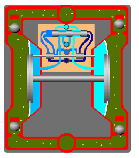
A pneumatic diaphragm pump uses compressed air as its power source to transport liquid through the reciprocating motion of diaphragms. Its structure is relatively simple, consisting primarily of the following components:
Pump Body: The outer casing of the pump, typically made of metal or corrosion-resistant plastic, containing internal channels for liquid flow.
Diaphragm: The core component, usually made of an elastic material such as rubber or PTFE; it oscillates back and forth to generate suction and pressure.
Check Valves (Ball Valves): There are two for each pump chamber—one at the inlet and one at the outlet. Acting like one-way gates, they ensure liquid flows in only one direction.
Pneumatic Drive Section (Air Motor): This is the pump’s power source, responsible for converting the energy of compressed air into the reciprocating motion of the diaphragms. It contains a main valve and a directional control valve that automatically switch the airflow direction.
Working Principle: The pump operates via an alternating suction and discharge cycle, a process similar to squeezing toothpaste out of a tube.
Continuous Cycling: The directional control valve within the air motor automatically switches the airflow direction, causing the two diaphragms to alternate between suction and discharge actions. This continuous cycle enables the steady transport of liquid.
Suction Process: Compressed air enters the air motor, pushing the diaphragm on one side inward while simultaneously driving the diaphragm on the opposite side via a connecting rod. This increases the volume of the pump chamber on that side, creating negative pressure (a vacuum); atmospheric pressure forces the inlet check valve open, drawing liquid into the chamber.
Discharge Process: Simultaneously, the volume of the pump chamber on the other side decreases, compressing the liquid inside and raising the pressure. This closes the inlet valve and forces the outlet valve open, expelling the liquid.
What are the advantages and disadvantages of pneumatic diaphragm pumps?
Advantages
Safety and Explosion-Proof: Powered by compressed air, it generates no electric sparks, making it suitable for flammable and explosive environments.
Capable of Prolonged Dry Running: Brief dry running causes no damage to the pump; however, dry running for more than 30 minutes is not recommended to avoid accelerated diaphragm wear.
Low Shear Force: The reciprocating motion of the diaphragm is gentle and involves no high-speed impeller agitation, preserving the material’s physical structure and chemical activity. The shear rate is far lower than that of centrifugal pumps, making it ideal for shear-sensitive materials such as emulsions, biological cultures, and polymer solutions.
Strong Self-Priming Capability: No priming water is required at startup; the maximum self-priming lift is typically up to 7 meters.
Excellent Handling Capabilities: First, it is resistant to clogging; it can typically handle particles with diameters of 1–10 mm and transport media with high solids content, such as sludge, mineral slurry, and sewage. Second, it can handle high-viscosity media. Additionally, it can transport highly corrosive liquids, with pump materials selectable based on the specific medium.
Easy Installation: Compact structure; no complex base is required—simply connect the air supply line and the fluid inlet/outlet piping to operate.
Adjustable Flow Rate: Flow rate can be regulated by adjusting the opening of the air intake valve.
Disadvantages
Reliance on Air Supply: Requires a stable air supply with high air quality standards; moisture or oil content can damage the internal air valve.
Limited Flow Rate: Mainstream industrial models have a maximum flow rate of approximately 60 m³/h, which is relatively low compared to centrifugal pumps of the same size. Furthermore, while large-bore pumps (e.g., 4-inch) offer higher flow rates, the pulsation is more pronounced.
Higher Energy Consumption: Under identical operating conditions, the operating cost is approximately 3–5 times that of an electric pump.
High Noise Levels: Operating noise typically ranges from 80 to 95 decibels, with particularly noticeable noise during exhaust. Installing a silencer is recommended to reduce noise levels to around 70 decibels.
Pulsation: The reciprocating motion of the diaphragm causes periodic fluctuations in the output flow. Installing a pulsation dampener can reduce flow fluctuation to within ±5%.
How do pneumatic diaphragm pumps differ from other types of pumps?
Air-Operated Diaphragm Pumps vs. Centrifugal Pumps
| Comparison Dimension | Pneumatic Diaphragm Pump | Centrifugal Pump |
|---|---|---|
| Power Source | Compressed air | Electricity (motor) |
| Working Principle | Reciprocating diaphragm motion; transfer via suction and discharge | High-speed impeller rotation generates centrifugal force to propel liquid |
| Flow Rate Range | Approx. 0.5–50 m³/h | Up to over 1000 m³/h |
| Head Range | Max. approx. 80 m | Max. up to several hundred meters |
| Self-priming Ability | Strong; dry suction lift of approx. 5–7 m | Weak; usually requires priming before startup |
| Dry Running | ✅ Can run dry; unlikely to be damaged | ❌ Dry running prohibited; may damage seals |
| Particle Handling | ✅ Handles particles; some models pass 10mm particles | ❌ Impeller prone to clogging and wear |
| High-viscosity Media | ✅ Suitable for high-viscosity liquids; wide viscosity range | ❌ Efficiency drops significantly with high viscosity |
| Shear Force | Low; minimal damage to material structure | High; impeller agitation creates significant shear |
| Explosion-proof | ✅ Compressed air driven; inherently explosion-proof | ❌ Requires explosion-proof motor and measures |
| Operating Efficiency | Approx. 20%–55% | Approx. 60%–85% |
| Noise Level | Relatively high; approx. 80–95 dB | Relatively low |
| Flow Characteristics | Pulsating flow | Smooth, continuous output |
| Wear Parts | Diaphragm, ball valves, valve seats | Mechanical seals, impeller, bearings |
| Max. Media Temp. | Usually -20°C to 120°C (material dependent) | Depends on seal and pump body materials |
In summary, centrifugal pumps are the cost-effective and efficient choice for stable operating conditions involving the continuous, high-volume transfer of fluids like clean water. Pneumatic diaphragm pumps are the reliable, worry-free choice for scenarios involving complex media, harsh operating conditions, or stringent safety requirements.
Pneumatic Diaphragm Pumps vs. Electric Diaphragm Pumps
| Comparison Dimension | Pneumatic Diaphragm Pump | Electric Diaphragm Pump |
|---|---|---|
| Power Source | Compressed air-driven | Motor-driven |
| Explosion-proof | ✅ Intrinsically safe; no risk of electrical sparks | ⚠️ Requires explosion-proof motor or design |
| Dry-running Ability | ✅ Can run dry for extended periods without damage | ⚠️ Can run briefly, but long-term dry running is not recommended |
| Submersibility | ✅ Some models can operate while fully submerged | ❌ Motor section cannot be submerged |
| Operating Noise | Higher (approx. 80–95 dB) | Lower (approx. 50–70 dB) |
| Flow Adjustment | Stepless adjustment via air pressure | Usually requires a variable frequency drive (VFD) |
| Flow Control Accuracy | Moderate | High (approx. ±1% accuracy with VFD control) |
| Flow Pulsation | Relatively significant | Relatively low |
| Energy Cost | Higher (relies on air compressor; lower overall efficiency) | Lower (direct motor drive; higher energy efficiency) |
| Air Source Dependency | Requires stable, clean compressed air | No air source required |
| Equipment Composition | Simple pump structure; no motor | Pump body + motor; more complex structure |
| Installation Flexibility | High (portable, rapid deployment, some submersible options) | Primarily fixed installation |
In summary, both pneumatic and electric diaphragm pumps are capable of handling complex media, with the core difference lying in their drive mechanisms. Generally, pneumatic diaphragm pumps are the preferred choice when a compressed air supply is available, explosion-proof capabilities are required, or operating conditions are harsh. Electric diaphragm pumps are selected when there is no air supply, noise control is a priority, the pump is used at a fixed station, or lower energy consumption is desired.
Pneumatic Diaphragm Pumps vs. Peristaltic Pumps
| Comparison Dimension | Pneumatic Diaphragm Pump | Peristaltic Pump (Hose Pump) |
|---|---|---|
| Product Positioning | Industrial transfer pump; suitable for complex operating conditions and high-flow transfer | Precision metering pump; suitable for clean, low-flow, high-precision transfer |
| Working Principle | Reciprocating diaphragm motion; transfer achieved via suction and discharge | Rollers continuously squeeze the hose; peristaltic action propels the fluid |
| Power Source | Compressed air | Electric motor drive |
| Wetted Parts | Diaphragm, ball valves, internal flow channels | Only the hose contacts the medium; pump body is completely isolated from the fluid |
| Hygiene/Cleanliness | Moderate; requires cleaning of pump chamber and flow channels | Excellent; changing the hose allows for media switching, reducing cross-contamination risk |
| Flow Accuracy | Moderate; affected by air pressure fluctuations | High; precisely controlled by adjusting motor speed |
| Minimum Flow Rate | Not suitable for ultra-low flow precision control | Capable of micro-flow transfer at the 0.01 mL/min level |
| Maximum Flow Rate | Approx. 50 m³/h | Typically ≤10 m³/h (large hose pumps can achieve higher rates) |
| Output Pressure | Max. approx. 0.8 MPa | Typically ≤1.6 MPa |
| Shear Force | Low; unlikely to damage the material | Extremely low; virtually no shear damage |
| Explosion-proof | ✅ Compressed air driven; intrinsically explosion-proof | ⚠️ Requires an explosion-proof motor |
| Operating costs | Relies on compressed air; overall energy consumption is relatively high | Motor-driven; long-term operating costs are generally lower |
Overall, both pneumatic diaphragm pumps and peristaltic pumps can handle corrosive, high-viscosity, and particle-laden media; both feature seal-less designs (eliminating leakage risks), adjustable flow rates, and self-priming capabilities, making them suitable for intermittent operation. However, pneumatic diaphragm pumps are the better choice for harsh operating conditions, such as flammable or explosive environments or locations lacking a stable power supply.
Pneumatic Diaphragm Pumps vs. Screw Pumps
| Comparison Dimension | Pneumatic Diaphragm Pump | Screw Pump |
|---|---|---|
| Product Positioning | Industrial transfer pump; suitable for harsh conditions and intermittent transfer | Continuous transfer pump; suitable for stable, high-precision, and high-viscosity media |
| Working Principle | Reciprocating diaphragm movement; transfers liquid via suction and discharge | Rotating screw forms continuous transfer cavities; pushes liquid forward |
| Power Source | Compressed air | Electric motor drive |
| Flow Characteristics | Pulsating; discontinuous flow | Smooth and continuous; virtually no pulsation |
| Flow Precision | Moderate; affected by air pressure and operating conditions | High; rotational speed and flow rate have a basically linear relationship |
| Self-priming Ability | Strong; dry suction lift of approx. 5–7 meters | Strong; can exceed 8 meters |
| Dry-running Capability | ✅ Can run dry for extended periods; unlikely to be damaged | ⚠️ Can run for short periods; prolonged dry running may damage the stator |
| Max. Viscosity | Approx. 30,000 cP | Up to 1,000,000 cP (e.g., asphalt, toothpaste, high-viscosity resin) |
| Particle Handling | ✅ Can pass large particles; up to 10mm for some models | Depends on screw structure and pitch; large particles may cause jamming |
| Output Pressure | Typically approx. 0.8 MPa | Up to 2.4 MPa or higher |
| Explosion-proof Performance | ✅ Compressed air driven; inherently explosion-proof | ⚠️ Requires an explosion-proof motor |
| Shear Force | Low; suitable for shear-sensitive media | Low; minimal damage to the medium |
| Structural Complexity | Simple structure; few parts | More complex structure; consists of rotor, stator, etc. |
| Operating Noise | Relatively high; approx. 80–95 dB | Relatively low; approx. 50–70 dB |
| Main Wear Parts | Diaphragm, ball valves, valve seats | Stator (rubber component), rotor |
In general, screw pumps are better suited for the continuous, long-term transfer of extremely high-viscosity media with low solids content, where stable flow and high discharge pressure are required. Conversely, pneumatic diaphragm pumps are better suited for harsh operating conditions—such as environments involving flammable or explosive materials, a lack of stable power supply, or frequent start-stop cycles—when transferring media containing large particles or grit.
Pneumatic Diaphragm Pumps vs. Gear Pumps
| Comparison Dimension | Pneumatic Diaphragm Pump | Gear Pump |
|---|---|---|
| Product Positioning | Suitable for complex media, harsh conditions, and intermittent transfer | Suitable for clean media, high pressure, and efficient continuous transfer |
| Working Principle | Reciprocating diaphragm movement; transfers liquid via suction and discharge | Meshing rotating gears; moves liquid via volumetric changes |
| Power Source | Compressed air | Electric motor drive |
| Wetted Parts | Diaphragm, ball valves, pump body flow channels | Gears, pump body, shaft seals |
| Flow Accuracy | Moderate; affected by air pressure fluctuations | High; flow rate is generally linear with rotational speed |
| Dry-Running Capability | ✅ Can run dry for extended periods without damage | ❌ Dry running not permitted; prone to gear wear |
| Media Cleanliness Requirement | Low; handles media containing particles and impurities | High; requires clean media to prevent gear damage from impurities |
| Particle Handling | ✅ Can pass some particles; up to 10mm for some models | ❌ Generally cannot pass solid particles |
| Output Pressure | Typically ~0.8 MPa | Up to 20–25 MPa (depending on structure and model) |
| Flow Rate Range | Approx. 0.5–50 m³/h | Approx. 0.3–300 m³/h |
| Shear Force | Low; minimal impact on shear-sensitive media | High; high-speed gear meshing generates shear |
| Explosion-Proof Capability | ✅ | Compressed air-driven; inherently explosion-proof |
| Corrosion resistance | High; options include PP, PVDF, stainless steel, etc. | Moderate; gears are typically metal, limiting use with corrosive media |
| Operating efficiency | Approx. 20%–55% | Approx. 60%–90% |
| Operating noise | Relatively high (approx. 80–95 dB) | Relatively low, though gear meshing noise is present |
| Key wear parts | Diaphragms, ball valves, valve seats | Gears, shaft seals, bearings |
| Maintenance complexity | Simple; easy to disassemble and maintain | More complex; requires pump disassembly to inspect internal parts |
Overall, pneumatic diaphragm pumps are more suitable when the medium contains impurities or particles, or in applications requiring explosion-proof capabilities, frequent start-stop cycles, or operation without a stable power supply.
When is an air-operated double-diaphragm (AODD) pump the right choice?
Based on the previous discussion regarding their working principles, pros and cons, and comparisons with other pump types, it is evident that AODD pumps are the preferred choice for applications requiring explosion-proof capabilities, handling complex media (containing impurities, particles, or corrosive substances), operating under unstable conditions (intermittent use or varying locations), or where a stable power supply is unavailable. Conversely, they are unsuitable for scenarios involving high-flow clean water, long-term continuous operation, high-pressure output or precision metering requirements, a lack of compressed air supply, or noise-sensitive environments.
How do you select the right air-operated double-diaphragm pump?
Selecting a suitable diaphragm pump involves considering multiple factors, including media characteristics (corrosiveness, viscosity, particle content, temperature, etc.), operating parameters (flow rate, head, port size, etc.), and the working environment (air supply, installation location, etc.). Pump selection is a complex, systematic process; choosing a pump that matches the specific operating conditions is essential to ensure efficient, safe equipment operation and to extend the pump’s service life.
Liquid Characteristics:
Media characteristics include corrosiveness, viscosity, particle content, temperature, and toxicity or flammability. Viscosity refers to the resistance a fluid encounters when flowing. For example, the viscosity of water is 1 centipoise (cP), ketchup is 50,000 cP, and toothpaste is 190,000 cP. Different liquid characteristics require different pump materials and specifications. Below is a classification of media characteristics and the corresponding pump materials required:
- When the medium is clean water or a neutral liquid, the pump body is typically made of aluminum alloy or cast iron; choose aluminum alloy for portability and cast iron for durability. Diaphragms are usually made of nitrile rubber, which is cost-effective and durable. Port sizes are selected based on requirements—1/2″ to 1″ are the most common—though if the water contains small amounts of silt or sand, it is advisable to choose a larger port size to reduce wear. 2. For oil-based media (lubricating oil, hydraulic oil, fuel, etc.): Pump bodies are typically made of aluminum alloy or cast iron (or 304 stainless steel for food-grade applications). Diaphragms are usually made of Nitrile rubber (NBR) or Fluororubber (FKM); standard natural rubber diaphragms must be avoided, as they swell rapidly and fail upon contact with oil. Additionally, for high-viscosity fluids like gear oil or heavy oil, larger port sizes and lower air pressure are required.
- For conventional acidic or alkaline liquids: If concentration is <30% and temperature is <60°C, the pump body is typically PP and the diaphragm is EPDM. If concentration is <50% and temperature is <80°C, the pump body is typically PVDF and the diaphragm is PTFE. If concentration is >50% or temperature is >80°C, the pump body is typically steel-lined PTFE and the diaphragm is PTFE.
- For highly corrosive media (concentrated acids/alkalis, strong oxidizers, etc.): Pump bodies are typically PVDF or steel-lined PTFE; diaphragms and ball valves use PTFE. Note that diluting concentrated sulfuric acid generates heat, causing rapid temperature spikes; steel-lined PTFE is required to ensure structural strength.
- For organic solvents (acetone, alcohol, benzene, esters, etc.): Due to the high permeability of these solvents through rubber, pump bodies are typically 316L stainless steel or PVDF, and diaphragms are PTFE. Additionally, for flammable or explosive solvents, a conductive pump body and reliable grounding (<100Ω) are required to prevent static sparks.
- For media containing solid particles (slurry, mineral pulp, sewage, ceramic slip, etc.): Pump bodies are made of wear-resistant metal, and diaphragms use wear-resistant Nitrile rubber (NBR) or Neoprene (CR). Additionally, particle diameter must be less than one-third of the pump’s maximum particle passage size. 7. For high-viscosity media such as glues, resins, inks, or sealants: The pump body should be made of aluminum alloy or stainless steel. Diaphragms should be made of Nitrile rubber (for viscosity <10,000 cP) or Fluoroelastomer/FKM (for viscosity >10,000 cP). Air pressure is typically controlled between 0.3 and 0.5 MPa. Additionally, if the viscosity exceeds 30,000 cP, switching to a screw pump is recommended.
- For shear-sensitive media such as emulsions, protein solutions, microbial cultures, or cosmetics: The pump body typically utilizes sanitary-grade 316L stainless steel or PVDF, while diaphragms use PTFE or FDA-certified silicone. Recommended measures include using easy-to-clean sanitary clamp connections, installing a pulsation dampener to minimize flow fluctuations, and operating at low speeds to reduce shear forces.
- High-temperature media (>80°C): For temperatures <60°C, standard rubber diaphragms (Nitrile/EPDM) are suitable. For temperatures between 60°C and 120°C, Fluoroelastomer (FKM) diaphragms—which offer superior heat resistance—should be used. For temperatures between 120°C and 200°C, PTFE diaphragms are required. Regarding the pump body, 316L stainless steel or PVDF should be used, as the structural strength of aluminum alloy decreases at high temperatures.
Operating Parameters:
Flow Rate: First, determine the actual volume of liquid (in cubic meters or liters) to be transferred per hour to establish the required flow rate. Note that the nominal flow rate of a diaphragm pump represents the maximum capacity under ideal conditions; actual operational flow is typically only 50%–60% of this nominal value. Additionally, it is advisable to include a 10%–15% margin above the calculated requirement to account for pipeline losses, fluctuations in medium viscosity, and flow rate degradation due to diaphragm aging.
Head (Lift): Head refers to the distance—both vertical and horizontal—to which the liquid must be “pushed.” It is calculated as follows: Head = Vertical lift height + Horizontal pipeline losses + Losses from elbows and valves. A simplified estimation method is as follows: every 1 meter of vertical lift equals 1 meter of head; every 20 meters of horizontal piping results in a head loss of approximately 1 meter; and each 90° elbow causes a head loss of about 0.5–1 meter. After calculating the actual required head, it is recommended to include a safety margin of 5%–10%. Additionally, the head is determined by air pressure—higher pressure yields greater head—but excessive pressure accelerates diaphragm wear; consequently, the maximum head for pneumatic diaphragm pumps typically ranges from 50 to 80 meters.
Port Size Selection: Port size refers to the internal diameter of the pump inlet/outlet. Sizes of 1/4″–1/2″ are generally suitable for low-flow, precision operations such as laboratory work or dispensing; 1″ is the most common industrial size; 1.5″–2″ sizes are suitable for media containing particles and for high-flow transfer; and 3″–4″ sizes are typically used in applications replacing centrifugal pumps. However, when conveying media containing particles or highly viscous fluids, the port size should be increased by one or two increments.
Operating Environment:
Ambient Temperature: Typically, the standard operating temperature range for pneumatic diaphragm pumps is 5°C to 65°C. If the ambient temperature falls below 0°C, residual moisture in the compressed air may freeze and clog the air lines; it is recommended to install a drying filter at the air source or select a model with anti-freezing capabilities. At ambient temperatures above 50°C, air valve seals age more rapidly and diaphragm lifespan is significantly reduced; selecting a fluororubber (FKM) diaphragm instead of the standard nitrile (NBR) version is recommended.
Air Humidity and Cleanliness: Pneumatic diaphragm pumps require dry, clean compressed air. Air sources containing moisture or oil can corrode internal air valves, leading to sluggish switching and reduced efficiency. In humid environments (relative humidity >80%), an oil-water separator must be installed. Air dryer; in dusty environments such as mines or cement plants, it is recommended to install a filter at the air inlet to prevent dust from entering the air motor and causing wear on the slide valve.
Flammable and explosive environments:Pneumatic diaphragm pumps powered by compressed air are recommended for these environments to avoid the generation of electrical sparks. However, when transferring flammable liquids, the pump body must be treated for electrical conductivity and reliably grounded (with a grounding resistance of <100Ω) to prevent static electricity accumulation and sparking. Additionally, the exhaust outlet must be vented to a safe area, as the exhaust may contain flammable vapors.
Noise requirements: The operating noise of pneumatic diaphragm pumps typically ranges from 80 to 95 decibels. If installed near office areas, indoors, or in manned spaces, installing a muffler can reduce the noise level to approximately 70 decibels. For applications with stricter noise requirements, a sound-insulating enclosure can be added, or an alternative pump type meeting the necessary criteria can be selected.
Common Faults and Solutions for Air-Operated Diaphragm Pump
| Fault Symptom | Possible Cause | Solution |
|---|---|---|
| Pump completely stops running | Insufficient air supply pressure | Check whether the air compressor is supplying air normally. |
| Inlet air filter clogged | Clean or replace the filter screen. | |
| Air valve jammed by impurities | Disassemble and clean the air valve; replace the worn O-rings. | |
| Worn main shaft or O-rings | Replace the worn parts. | |
| Pump makes a “slapping” sound but discharges no liquid | Diaphragm ruptured | Replace the diaphragm. |
| Ball valve jammed by foreign matter | Disassemble the pump head and remove the foreign matter. | |
| Inlet piping / fittings leaking air | Tighten the clamps to ensure a proper seal. | |
| Suction lift too high | Move the pump closer to the liquid source and keep it within 4 m. | |
| Inlet blocked | Clean the inlet filter. | |
| Pump runs and makes sound, but flow is clearly insufficient | Ball valve worn or poorly sealed | Replace the ball valve / ball seat. |
| Diaphragm cracked | Replace the diaphragm. | |
| Air pressure too low | Adjust to 0.4–0.7 MPa. | |
| Medium viscosity too high | Reduce air pressure to 0.3–0.5 MPa or increase the pump port size. | |
| Flow fluctuates / is irregular (irregular slapping sound) | Unstable air supply pressure | Install a pressure-regulating valve. |
| Ball valve not seated correctly | Disassemble, inspect and clean the ball valve and its seat. | |
| Uneven force on both sides of the diaphragm | Check whether the left and right diaphragms are worn equally. | |
| Liquid leaks from the pump body (seeps from the body seams) | Diaphragm ruptured / perforated | Replace the diaphragm. |
| Sealing surface worn or fouled | Clean or replace the sealing surface. | |
| Loose clamps | Re-tighten in a diagonal sequence. | |
| Liquid discharged from the exhaust port | Ruptured diaphragm (most common) | Shut down immediately and replace the diaphragm. |
| Diaphragm not installed properly | Reinstall and tighten. | |
| Air bubbles in the outlet liquid | Diaphragm cracked | Replace the diaphragm. |
| Inlet piping / fittings leaking air | Focus on checking whether the inlet-side clamp is fully tightened. | |
| Abnormal noise or excessive vibration | Base not firmly fixed | Re-tighten the base bolts. |
| Worn internal ball valves / bearings | Disassemble, inspect and replace. | |
| Medium contains large particles | Install a filter. | |
| Air pressure too high | Reduce to the recommended range. | |
| Muffler (silencer) clogged | Clean or replace the muffler. | |
| Air valve icing | Moisture content of compressed air too high | Install an air dryer. |
| Low ambient temperature | Improve insulation. |
How to Minimize Air-Operated Diaphragm Pump Failures?
Protect the Diaphragm: The diaphragm is a critical wear part; protecting it extends the pump’s service life and reduces maintenance costs. Maintain air pressure within the optimal range of 0.4–0.7 MPa; excessive pressure can cause the diaphragm to rupture. Avoid prolonged operation against backpressure (e.g., with the discharge valve closed for too long), as uneven stress can lead to diaphragm deformation and fatigue. When pumping high-viscosity media, lower the air pressure; excessive pressure prevents the diaphragm from rebounding in time, resulting in reduced efficiency and potential damage. Finally, regular replacement of the diaphragm is essential.
Ensure a Clean, Dry Air Supply: Air-operated diaphragm pumps require clean, dry compressed air; air supplies containing moisture or oil can corrode the pump’s internal components. Install an oil-water separator in humid environments and an air inlet filter in dusty environments. Additionally, regularly clean filter screens and inspect internal components such as air valve pistons and O-rings.
Pipeline Maintenance: Ensure a tight seal at the pump inlet and periodically check that clamps are tightened in a diagonal sequence. When handling media containing particulates, install an inlet filter to prevent large particles from jamming ball valves or accelerating diaphragm wear. Since pump vibrations transfer to the piping—potentially causing loose connections or pipe fractures over time—installing flexible hoses at rigid pipe joints can act as a buffer to protect the system. Finally, drain residual fluid from the lines after shutdown; corrosive residue left in the pump chamber can cause ongoing damage to the diaphragm and sealing surfaces.